
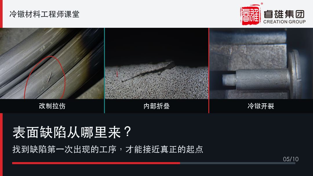
When cracks are found on the head, flange edge, or R-corner at the cold heading site, many people’s first reaction is to inspect the material or the cold heading die.
Surface defects can be inherited from upstream processes or newly generated in intermediate operations. Cold heading changes the morphology of defects but cannot restore the continuity of material that has already been damaged.
Defect Path: Continuous Casting Billet → Rolled Wire Rod → Transportation and Handling → Pickling and Reconditioning → Drawing and Wire Passing → Cold Heading Forming
I. Continuous Casting Stage: Defects May Begin Below the Surface of the Billet
The billet is the starting point for wire rod production. Abnormal oscillation marks, subsurface porosity, slag inclusions, scale scars, and pits can all become sources of subsequent surface defects.
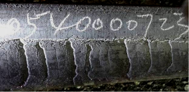
Figure 1: Abnormal oscillation marks on a continuous casting billet. Normal shallow oscillation marks do not constitute defects; only when these marks become unusually deep or are accompanied by cracks or slag inclusions at their base does the risk significantly increase.
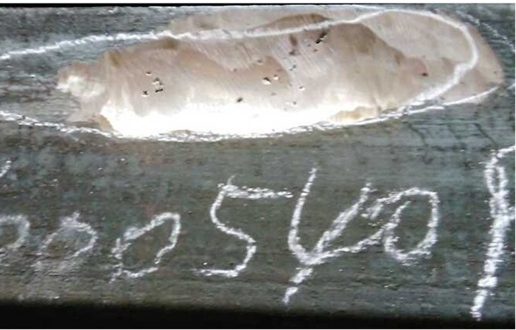
Figure 2: Subsurface porosity exposed after grinding. During rolling, such pores may be compressed closed, or they might elongate along the rolling direction; whether their inner walls have oxidized will affect whether they can be reliably welded shut later on.
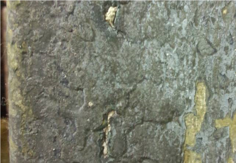
Figure 3: Slag inclusion on or near the surface of the billet. Since slag phases cannot deform compatibly with the steel matrix, they may fracture, elongate during rolling, and evolve into scale scars, folds, or linear defects.
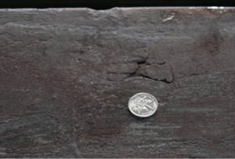
Figure 4: Surface scale scar on a steel billet. Flaky metallic attachments may be flattened and rolled into the substrate during subsequent rolling operations; although the surface appears smooth, the internal interface may not truly bond.
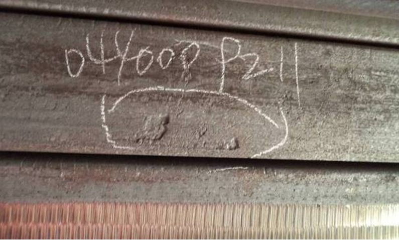
Figure 5: Surface pits on a steel billet. The term “pit” refers to the observed morphology; its specific origin must be determined by examining oxides at the pit bottom, edge curling, and surrounding cracks.
Surface defects on the billet may be compressed, elongated, or redirected during the rolling process. Even if the surface appears smooth afterward, it does not mean that the original material discontinuities have disappeared.
II. Rolling Phase: Defects May Be Extended or Recreated
Cracks in the billet can evolve into longitudinal cracks in the wire rod, scale and slag inclusions may be flattened and elongated, and subsurface blowholes can also form intermittent linear anomalies.
The rolling process itself can also generate defects. Poor die filling, misaligned guide devices, or abnormal roll gap conditions can lead to the formation of ears; when these ears are pressed back onto the material surface in subsequent passes, they may create folds. Similarly, oxide scale or foreign particles pressed into the base metal will leave localized areas of discontinuity.
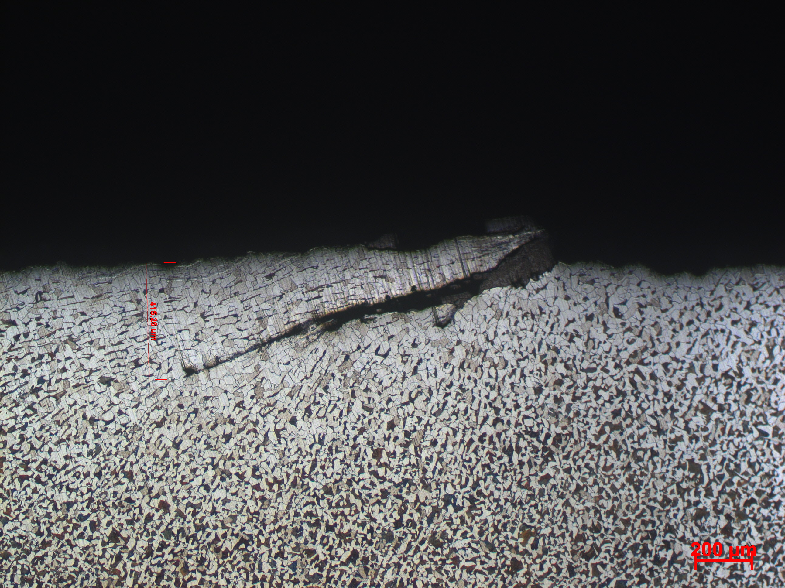
Figure 6: Cross-section of a folding defect. The surface metal is folded inward like a tongue, with no reliable bonding at the interface. Although the surface appears temporarily closed, this does not mean the internal defect has been eliminated.
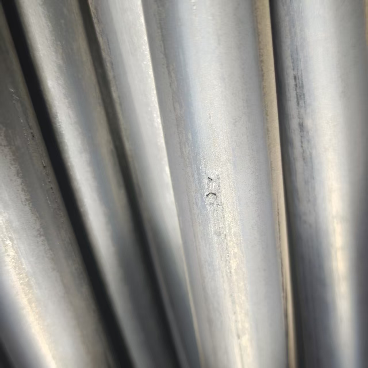
Figure 7: Surface scaling on wire rod. Compared with ordinary scratches, scaling often exhibits flaky attachments, local edge lifting, or signs of spalling.
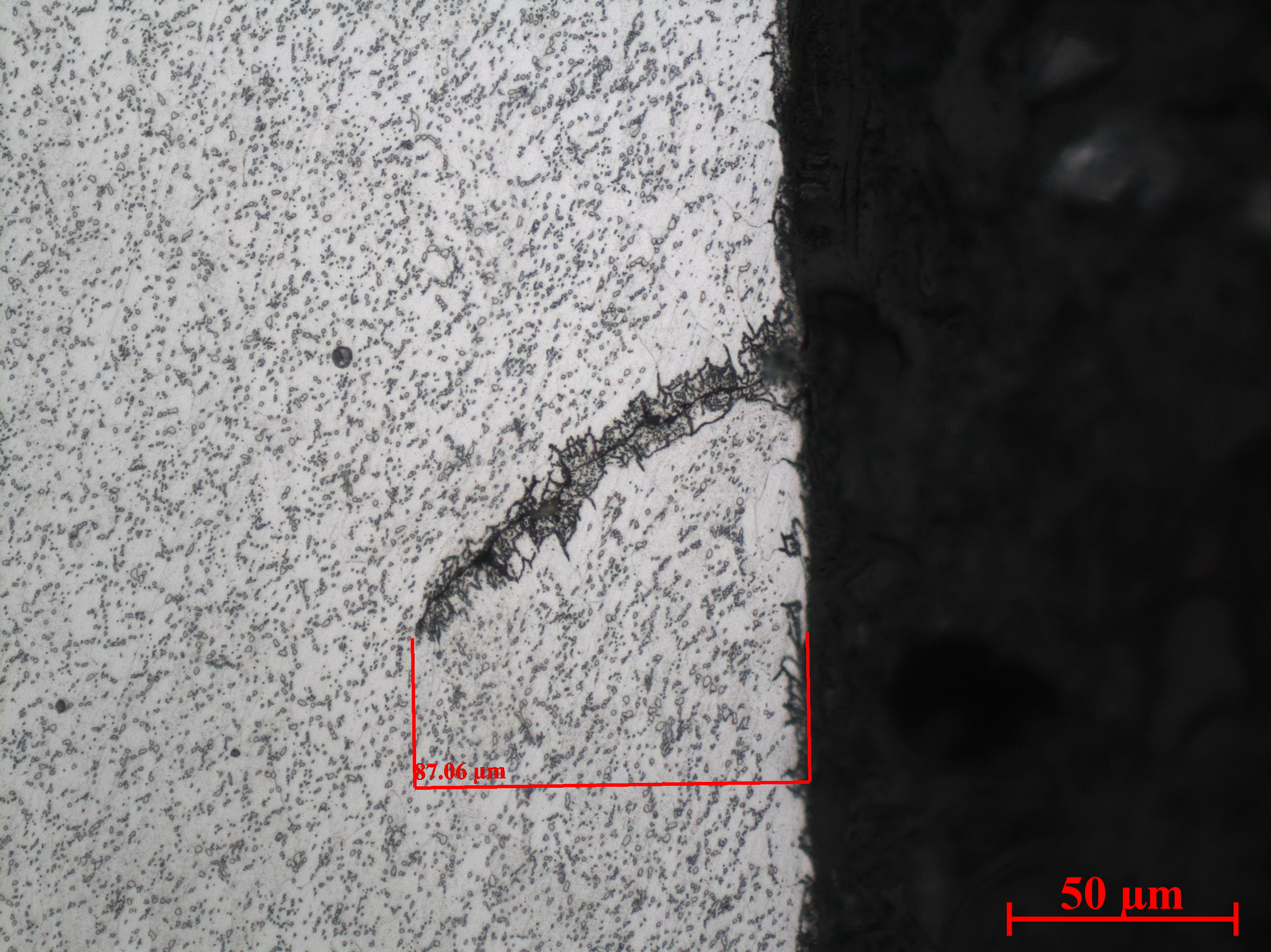
Figure 8: Cross-section of surface cracks on wire rod. The crack shown extends from the surface toward the interior of the base metal; whether it is accompanied by oxidation, decarburization, or abnormal microstructure requires further analysis.
The appearance of folds and cracks can sometimes be similar, but their formation mechanisms differ. Folds occur when portions of metal are involuted without achieving reliable bonding, whereas cracks represent actual separations in the continuity of the base material. Therefore, tracing their origins cannot be treated interchangeably.
III. Transport and Transshipment: Impact Scratches May Become Fracture Nuclei
During hoisting, coiling, stacking, and transportation, coils may collide, drag against surfaces, or rub against each other, resulting in scratches, indentations, and metal burrs. Such damage is typically localized and random, often concentrating on the outer layers of the coil or at points of contact during handling.
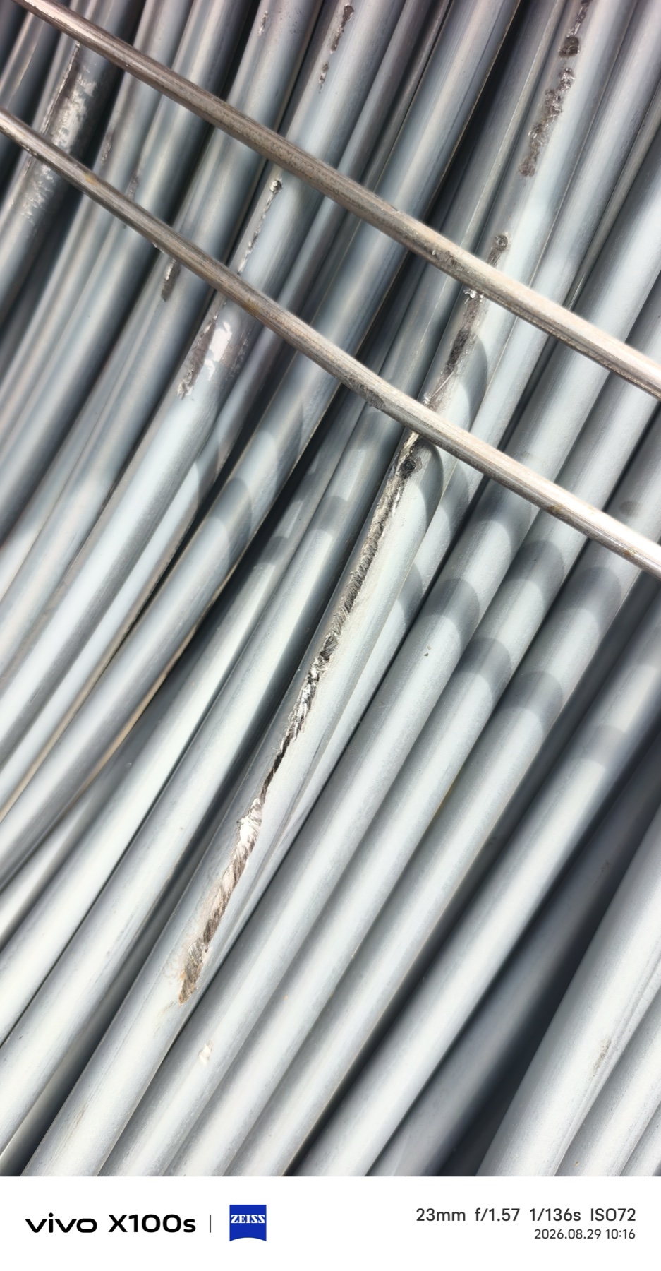
Figure 9: Scratches and impacts caused by transport or transshipment. Their orientation and location are usually irregular, differing from continuous longitudinal scratches produced by wire-drawing dies.
For products subjected to moderate deformation, minor damage may not immediately result in abnormalities; however, once such damage occurs in high-deformation, complex-head, or thin-flange components, the damaged areas can become stress concentration points and be amplified during cold heading processes.
IV. Acid Washing Stage: May Expose Defects and Also Leave Hidden Dangers
After acid washing removes the oxide scale, previously concealed cracks, folds, scars, and pits gradually become visible. Therefore, discovering defects after acid washing does not necessarily mean that these defects originated during the acid-washing process.
If the oxide scale is not thoroughly removed, residual oxides can interfere with the uniform formation of the phosphating film and may break up, flake off, or be pressed into the wire surface during drawing.
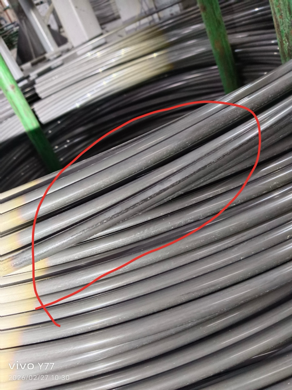
Figure 10: Residual oxide scale after acid washing. The dark longitudinal bands still need to be distinguished from oxide residues inside folds or cracks; conclusions should not be drawn solely on color.
Inadequate control of the acid-washing process can also lead to pitting corrosion and surface roughness. To determine whether the problem stems from originally existing defects being exposed or from new defects introduced during acid washing, it is necessary to retain samples both before and after acid washing for comparison.
V. Modified Drawing: Longitudinal Scratches Are Newly Added Defects That Are Easily Underestimated
The modification process not only changes the dimensions of the material but can also directly damage the wire surface.
Worn wire-drawing dies, oxide scale or metal chips entering the die holes, temporary failure of the lubrication film, as well as burrs or abnormal contact at guide wheels and guiding components, can all cause continuous or intermittent longitudinal scratches.
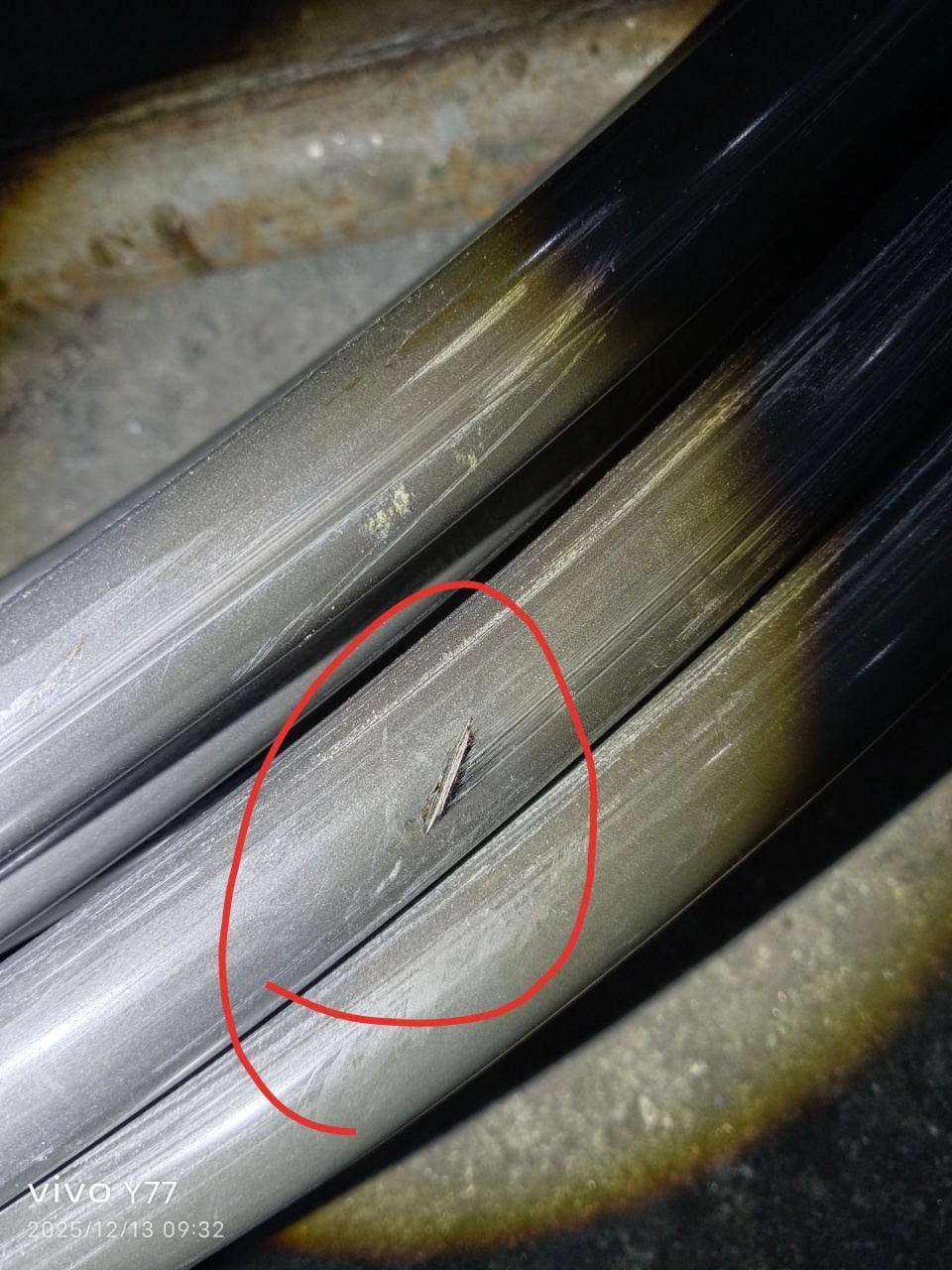
Figure 11: Localized scratches produced during modified drawing. These defects are distributed along the length of the wire and are accompanied by grooves, raised metal, or localized tearing.
For short-distance, sporadic scratches, attention should be paid to hard foreign particles, momentary adhesion of material, and localized contact; whereas if the scratches appear continuously over long distances with relatively fixed circumferential positions, the focus should be on inspecting the wire-drawing dies, guide wheels, and wire-passing points.
However, longitudinal marks do not necessarily originate from the drawing process. Rolling-induced cracks, folds, and residual oxide scale may also exhibit similar appearances after drawing. What truly needs to be confirmed is whether the defect already existed before entering the drawing stage, or whether it began to appear only after passing through a particular die or wire-passing point.
This chapter discusses only surface damage caused by drawing. The effects of reduction ratio, number of drawing passes, and work hardening on cold-heading performance will be addressed separately in Chapter Six.
VI. Cold Heading Front End: The Last Newly Added Defect Is Often Overlooked
Even after the material enters the cold-heading machine but before formal shaping begins, new surface damage can still occur. Guide wheels, straightening devices, and feeding mechanisms may scratch the wire; wear, chipping, and burrs on shearing blades or shearing dies can also damage the end faces or sides of the blanks.
If defects consistently appear in a fixed direction and at a fixed location, or if they change noticeably after replacing guide wheels or shearing blades, then simply rechecking the material certificates and original coils is insufficient.
VII. Why Do Defects Get “Inherited” All the Way to the Finished Product?
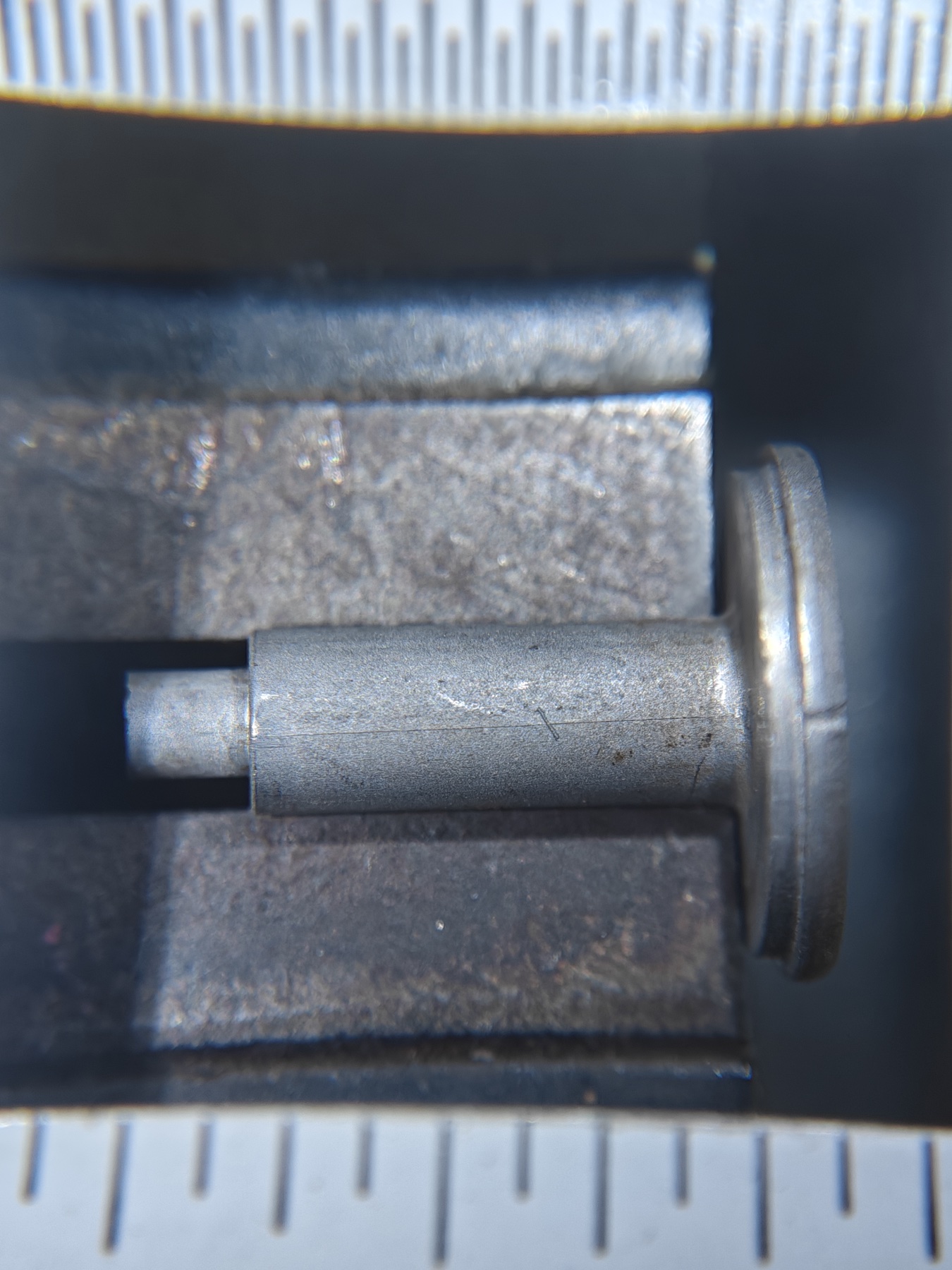
Figure 12: Cracking at the edge of the flange on a cold-headed finished part. The photograph shows where the defect ultimately manifests; one should not assume the defect originated in the material simply based on its appearance.
Defects are not simply replicated in the finished product; rather, they persist through each process stage, changing form along the way.
VIII. To Determine the Origin of a Defect, Find Its “First Appearance”
Engineer’s Perspective
A defect in the finished product is merely the outcome; only by locating the process stage where the defect first appeared can we get closer to its true origin.
The purpose of defect tracing is not to apportion responsibility upfront, but to establish a complete evidentiary chain across all production stages.
If you’re also encountering issues such as scale scars on wire coils, longitudinal scratches, folds, or occasional cracking during cold heading, please send me details including material grade, dimensions, defect photos, affected workstations, and the distribution pattern of anomalies. I can help assess whether your investigation should begin with raw materials from the steel mill, transport protection measures, pickling and re-drawing procedures, or equipment-related aspects of the cold-heading process.
Next Episode Preview
Chapter Six: “Why Do Identical Materials Behave Differently After Drawing and Cold Heading?”
This chapter will focus on how reduction ratio, drawing passes, and work hardening alter the actual condition of the material as it enters the cold-heading machine.